Titan: Difference between revisions
No edit summary |
No edit summary |
||
| Line 25: | Line 25: | ||
Different bitstreams are required for Shiva, and the various revisions of Waternoose, due to difference in [[Power On Reset]]. | Different bitstreams are required for Shiva, and the various revisions of Waternoose, due to difference in [[Power On Reset]]. | ||
The DIP switch operation is specific to the firmware version. The recommended configuration for DD1 | The DIP switch operation is specific to the firmware version. The recommended configuration for DD1 is OFF - OFF - ON - OFF. | ||
=== LEDs === | === LEDs === | ||
Revision as of 10:56, 13 June 2023
 Titan II | |
| Designed By | IBM |
|---|---|
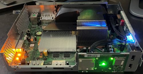
Titan is a development board used during bringup of the Shiva and Waternoose Engineering Sample CPUs. It also allows an IBM RISCWatch to be used to debug and test the processors.
Specifications
- Xilinx Spartan 3 XC3S200 FPGA
- 128KB Xilinx XCF01S JTAG PROM
- 4 DIP Switches
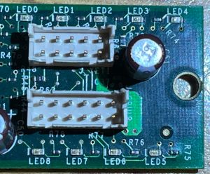
- 9 3.3V LEDs (Titan II only)
- 50MHz 3.3V Crystal
Details
There are two versions, the Titan and the Titan II.
The Titan is powered off the console via the 3.3V V_MEMPORT. This is stepped down to 2.5V and 1.2V. Titan used on Shiva receive 1.3V from V_CPUCORE. Titan used on Waternoose receive 1.8V from V_1P8.
The 10-pin J_YETI header connects to J8C1, the CPU JTAG header, while the 12-pin J_GPUL header connects to J7G2, the Shiva GPUL JTAG header.
Different bitstreams are required for Shiva, and the various revisions of Waternoose, due to difference in Power On Reset.
The DIP switch operation is specific to the firmware version. The recommended configuration for DD1 is OFF - OFF - ON - OFF.
LEDs
The Titan II has 9 LEDs mounted near one end. Reverse engineering has been used to determine their meaning. Earlier Titan revisions do not have LEDs, as the GPIOs that control them are connected to the J_GPUL header for Shiva. As a result, Titan II boards cannot use Shiva firmware.
For DD1 Firmware:
- LED 0 through LED 4 are blue LEDs that indicate the status code between 0x00 and 0x1F. Bit 0 (LED 0) is MSB.
- LED 5 is a red LED that indicates when the Titan times out when attempting to boot the CPU.
- LED 6 is a green LED that indicates booting priority is Secure ROM.
- LED 7 is a yellow LED that indicates booting priority is Sysver.
- LED 8 is a red LED that indicates that the cores will be held for RISCWatch use.
Gallery

